Originally constructed between 1955 and 1959, the Auckland Harbour Bridge is New Zealand’s largest bridge and the one with the largest span.
With only vehicular and passenger ferries available for access to the North Shore, by the mid-20th century the need for a bridge across the Waitemata Harbour was a pressing matter. There had been several attempts to have a bridge constructed dating from the 1860s, with the first serious plan advancing in the late-1920s only to be stopped by the Great Depression. From the mid-1940s Sir John Allum began promoting the idea and this time it went ahead.
After three Royal Commissions the Auckland Harbour Bridge Authority was formed in 1951, and built the bridge as a toll structure using loan money. It was agreed that the connecting motorways would be provided by the National Roads Board.
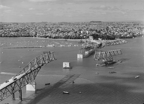
Auckland Harbour Bridge under construction [29 November 1958]. Whites Aviation Ltd: Photographs. Ref: WA-48833-G. Alexander Turnbull Library, Wellington, New Zealand. http://natlib.govt.nz/records/22344644.
Constructing the Auckland Harbour Bridge
Allum went to England to have the bridge designed by Freeman Fox and Partners, and it was built by the Cleveland Bridge and Dorman Long Joint Venture. Hundreds of labourers were employed on the project over the four year construction period, including 180 men sent out from England. At times progress on construction was slow with the workers frequently going on strike in 1956 and 1957. The hazardous nature of the work was highlighted by the deaths of four workers during the project. A plaque commemorating these men, who fell to their deaths, is located under the bridge at Stokes Point on the North Shore.
The bridge is 1,020 metres long and has 7 spans. Each span is identified by a letter, A at the north end to G at the south end. The navigation span, B, is 243.8 m with a 43.3 m clearance at high water.
There are in fact two bridges, A to C 597.4 m long and D to F 422.2 m long. There is a 1.7 m long toothed expansion joint between them, clearly visible in the roadway, but no structural connection.
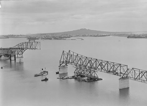
Auckland Harbour bridge under construction [1 December 1958]. Whites Aviation Ltd: Photographs. Ref: WA-48875-G. Alexander Turnbull Library, Wellington, New Zealand. http://natlib.govt.nz/records/22811100.
The 12.8 m wide roadway passes through the 14.7 m wide spans A, B and C. The roadway is above the 9.9 m wide spans D to F.
The construction of the superstructure was by assembly on falsework from the end anchorages and then in cantilever, except for span C. That span was erected on top of span F. Within span F there is the suspended span 6 held by large steel pins in the bottom chords. Steel pontoons were floated under span 6, the large steel pins removed and span 6 and span C were lifted by a rising tide and the whole 1,200 tons of steelwork floated and towed between the piers of span C. On a falling tide span C was lowered into place and span 6 returned to and pinned in its proper place. The spectacular floating structure was 177 m long and the highest point 49 m above sea level. This most ingenious and daring operation took six days because of adverse winds.
The Auckland Harbour Bridge's 'pick-a-back' span film clip in Te Ara - The Encyclopedia of New Zealand shows the bridge's spans being moved into place.
Having successfully navigated various construction and technical challenges, the Auckland Harbour Bridge was officially opened by the Governor General, Lord Cobham, on May 30 1959.
The video below shows the opening celebrations.
Ongoing construction and Auckland Harbour Bridge maintenance
Fortunately, the design of the piers was conservative and when the traffic grew at an extremely fast rate it was found that there was sufficient reserve to use the original piers for four extra lanes. The extensions, doubling the traffic lanes from four to eight, were added between 1968 and 1969. Nicknamed “Nippon clip-ons” because they were prefabricated in Japan, the extensions were built on the original bridge foundations and were of orthotropic box structure, which in the mid-1960s were at the forefront of technology.
However, much of the detailing incorporated into the extensions has been shown by subsequent research to be less than optimum in terms of fatigue performance. Fatigue cracks discovered in 1985 required the removal and replacement of some 2,000 splice joints in the stiffening troughs immediately below the bridge road surface.
Special techniques needed to be developed to enable pieces of the bridge to be safely removed while the bridge was still under dead load, and then replaced without causing welding distortions. The techniques also had to permit economic production rates because repairs could be undertaken outside peak hours only and the bridge could not be opened to traffic with incomplete repairs. Semi-automatic welding machines, using fluxed covered wires were utilised and extensive procedure trials were undertaken to develop techniques that met the demanding technical and time requirements for the work. These innovative techniques have been received with great interest in welding circles worldwide.
The “management” of fatigue effects is now an integral part of the maintenance of the extensions (clip-ons) to the bridge. Detailed analysis following discovery of the trough splice cracks in 1985 led to predictions of the fatigue life of the identified “at risk” details throughout the bridge. A detailed inspection manual defines the locations, inspection intervals, and techniques to be used as part of an ongoing programme. Formal quality assurance principles were applied to the two major welding repairs undertaken on the bridge between 1986 and 1989. Building on the experience gained in these two exercises, the consultants have now implemented quality assurance procedures for the bridge maintenance and painting contract.
Despite these fatigue problems, an interesting facet of the bridge was highlighted in a design study done on the clip-ons by the Ministry of Works and Development on behalf of the Auckland Regional Authority. This study determined that there is capacity on each of the clip-on bridges to carry a light rail line as well as two lanes of light traffic. Heavy lorry and bus traffic would then use the main centre bridge.
Aside from the “clip-ons” another interesting feature of the bridge is the moveable concrete traffic barrier, which was put in about 1989. This, apart from being a major safety device, allows tidal traffic flow on the bridge, greatly increasing its peak load capacity.
In 1984, rather than increase the tolls to cover repair and maintenance costs, the Harbour Bridge Authority offered the Bridge to the National Roads Board on condition that it be toll-free. Fortunately the National Roads Board was able to finance the million-dollar-plus annual maintenance cost of the bridge and it has become an integral part of the Auckland motorway system.
You can listen to a summary of the bridge's history from the Ministry for Culture and Heritage's Roadside Stories series.
Heritage recognition
IPENZ “Engineering to 1990” project
This item of New Zealand’s engineering heritage was recognised as part of the IPENZ “Engineering to 1990” project, which the Institution organised to help celebrate the country’s sesquicentenary in 1990. A plaque was unveiled to mark the significance of this bridge as part of the development of the nation.
More information
Access
There is no public pedestrian access to the bridge, although there is a commercial bridge walk experience operating.
Further reading
Auckland Harbour Bridge Authority 1951 – 1961. Auckland: Auckland Harbour Bridge, 1961.
A. W. Cliffe, 'Auckland Harbour Bridge,' New Zealand Engineering Vol.13:5 (May 1958) pp.202–03.
Renee Lang, Auckland Harbour Bridge: 50 years of a city icon. Auckland: Random House, 2009.
Related Record entries
Location
State Highway 1, Auckland.