Completed in 1964, Hamilton Rail Bridge, Waikato River, was constructed alongside its late 19th Century predecessor. It was a challenging project because of design parameters and construction restrictions.
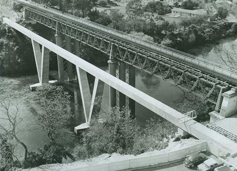
Hamilton Rail Bridge, circa 1963, Image courtesy of Opus International Consultants Ltd.
The North Island Main Trunk (NIMT) railway bypassed Hamilton’s city centre, but the (then) Thames branch line passed across the main street (Victoria Street) in the city centre at road level. With the growth of the city and increase of car traffic this caused considerable traffic problems and in the late 1950s it was decided the rail line needed to be lowered to pass underneath Victoria Street. This involved lowering the branch rail line coming from Frankton Junction and the construction of a new bridge across the adjacent Waikato River. New Zealand Railways commissioned the Ministry of Works (MoW) to design the bridge and the construction contract was let to Wilkins and Davies Construction Company Limited in 1961.
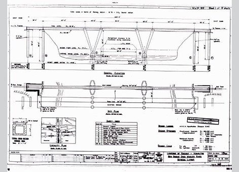
Plan of Hamilton Rail Bridge. Image courtesy of Opus International Consultants Ltd.
The concrete bridge is approximately 143 metres (m) long and wide enough to carry a single track railway across the Waikato River. The substructure consists of reinforced concrete piers and abutments founded on cast in situ piles and cylinders. The superstructure consists of seven spans of pre-stressed concrete box girder, two of which are land spans. The remaining spans cross the river some 18m above normal water level.
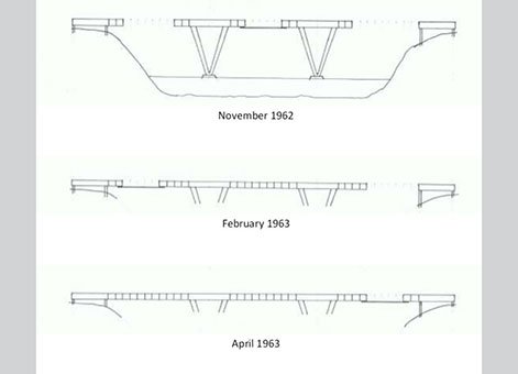
Second Hamilton Railway Bridge (1964) - stages of deck construction. Drawing by Rob Aspden, 2014. IPENZ.
Design and construction challenges
This project was interesting because the designers had to consider more than just the usual geometric requirements of the river crossing. The Government stated that the bridge had to be built in concrete (because of the much higher overseas cost of a steel structure) and continuity was required for earthquake resistance. Because the river is navigable the pier bases also had to be placed alongside the existing ones and the abutments of the bridge had to keep right away from the banks because of their poor strength due to their large deposit of pumice and volcanic ash.
Since navigational clearance had to be maintained during construction it was decided to erect the bridge using the cantilever process (see attachment below). A continuous prestressed concrete hollow box girder form was chosen. Its “contemporary” pier design (also hollow) met both the requirements of waterway and of superstructure rigidity.
Site access was difficult because of the inability to use the river bank, again because of the poor strength of the bank material, and the need to keep the navigable span open. Des Mataga (b.1933), who was involved early in the construction, noted “access was provided by a Wilkins and Davies designed cableway built by some very talented fitters from miscellaneous equipment”. In addition “a small number of lifts were made off the old bridge using the 40 tonne recovery crane owned by the Railways Department”. The sloping pier legs on each pilecap were raised evenly and tied together so there was never more than one lift of concrete out of balance.
The bridge deck structure was constructed out from the piers by cantilevering in 2.7 m blocks (cast in place) progressively stressing with Freyssinet type 100 ton cables. This was the first use of the 100 ton cable Freyssinet system in the country. Initially problems were encountered in the progressive stressing of the cantilevered sections which included the cable anchors, the positioning of, the clearances around and the friction in the cable ducts, and the quality control of the concrete. These problems were satisfactorily dealt with through careful action by MoW and contractor staff. This was an important learning process that would have been of great use in the design and construction of the Newmarket Viaduct, which occurred shortly after and again was led by Alfred William (Bill) Smith (b.1934) in the MoW Bridge Design Office in Head Office, Wellington.
The bridge makes an interesting and arresting contrast with the old Warren truss alongside, which was converted for road use. It is also a fine example of the mettle that is required in engineering innovation. To quote Bob Norman (b.1923):
“From Hamilton[Rail Bridge], there is a great lesson – one of raw courage.[The engineers involved] moved into unknown territory, where there were still many deficiencies in the various technologies involved. You have to be confident, and to take risks where you believe you can solve the problems as they arise.”
Find out more
Access
Hamilton Rail Bridge can be viewed any time from the pedestrian lanes of the neighbouring road bridge or from the Waikato River bank.
References
Railways – Lowering of Hamilton Railway – New Waikato Bridge. Archives New Zealand file, Item ID R17419143.
AW Smith, “The Newmarket Viaduct – Part 2: Design investigations and specification”, New Zealand Engineering Vol.20:12 (December 1965), p.498.
Location
Waikato River, Hamilton (next to the Claudelands Road bridge), Waikato.