15 May 2018
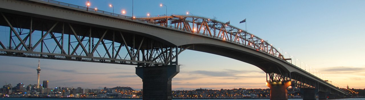
Engineering New Zealand member Brian Wilson spent four years working on the construction of the Auckland Harbour Bridge from 1955 – 1959. He’s developed an op-ed piece that examines some discrepancies he’s found in a recent article featured in Engineering Insight magazine last year.
Review of article “Connecting a city” in Volume 18/4 in Engineering INSIGHT August/September 2017.
The intent of the article is the heritage of the Auckland Harbour Bridge. Heritage is defined as “valued objects such as historical buildings that have been passed down from previous generations”. The article strays outside that definition introducing irrelevancies and matters not then built. It also has opinion which is not justified and descriptions that are inaccurate and misleading. Some events in the history of the bridge that are of interest to the present generation have not been addressed.
In 1951 the Auckland Harbour Bridge Authority commissioned a design and contract documents for a bridge with 5 vehicle lanes, 2 1.8m footpaths and service ducts with a clearance above high water of 43.3m in a navigation span of 243.9m. In June 1952 a tender was accepted subject to the availability of finance. The overall cost of the entire project of the bridge and the approaches was estimated to be £8,122,000.
In February 1954 the NZ government authorised loans only if the total cost could be reduced to £5,000,000. This limit was achieved by reducing the width to 12.8m for 4 vehicle lanes, no footpaths, reducing the quality of the protective treatment of the steel structure, and having only connections to Curran Street on the south side and Queen Street, Northcote on the North side and a small toll plaza on the reclaimed land at the south end.
A new design was prepared with a total estimated cost of £5,002,000. The contract price for the bridge was negotiated with the bidder accepted in June 1952 and a contract awarded to Cleveland Bridge and Dorman Long (Auckland) in October 1954. Work on site began on 1 May 1955.
During the construction of the bridge the Chairman of the Bridge Authority, Sir John Allum, managed to get additional finance. The intended full design of approaches, toll plaza and administration building, and the top quality protective treatment of a zinc sprayed coating were added. But it was not physically possible to put back the fifth lane and footpaths on the bridge.
That is how Auckland got a 4 lane bridge which was soon found to be inadequate. The 5 lane bridge with 2 footpaths would have cost only £770,000 more.
There is a lesson there for planners; do not start a project unless you have the resources for its main core elements. Ancillary elements can be added later.
There were frequent strikes for the usual claims for more money but not because of “the extremely dangerous nature of the work” as stated in the Insight article.
In 1951 the navigation span was for the passage of ships to the proposed future site of cargo berths in the Te Atatu area. Also, the bridge height was kept low for the take-off and landing of the Air Force flying boats to and from the maintenance base at Hobsonville. With the site restraints it is unlikely that a prestressed concrete structure could economically fulfill the need as speculated in the article.
In 1957 there was a mishap with the construction of pier 5, the second from the south end at Westhaven. When the cutting edge of the caisson was at 11.5m below mean sea level the pier tilted 27 degrees to the north and lost internal air pressure. The working chamber filled with marine mud which also entered the access shafts. Restraining tackle to the southern anchorage prevented further tilting and made entry safe to work in compressed air. Excavation of the mud started in the confined space of inclined access shafts with garden trowels and small buckets. Detailed investigation found strength of the mud on the north side was half that on the south side. No one was injured in the mishap.
The method of constructing the piers was developed for the tallest pier at the south end of the navigation span. The maximum depth below high tide of 33.3m was thought to be the maximum limit for safe working by men in compressed air as in a diving bell. Very strict procedures for compressing and decompressing miners excavating rock in the pier foundations were followed resulting in no serious case of the “bends”.
The rock at foundation level was much harder than anticipated in the design of the foundations. Tests of strength were done for the record. The foundations would be able to sustain a much greater load that was possible from the 4 lane bridge. This was of great benefit to the design of the 2 lane width extensions each side of the 4 lane bridge in 1965.
The piers in the harbour are numbered 1 to 6 starting from the north end below Stokes Point. The spans between piers are designated A to G from the north. At pier 3 there is the wide expansion joint between spans C an D. It was not possible to make any structural connection between the spans there.
The method of constructing span C between piers 2 and 3 was most ingenious. The following description is from the Heritage section of the EngineeringNZ.org web site to replace the whole first new paragraph on page 13 of the Insight article. “The construction of the superstructure was by assembly on falsework from the end anchorages and then in cantilever, except for span C. That span was erected on top of span F. Within span F there is the suspended span 6 held by large steel pins in the bottom chords. Steel pontoons were floated under span 6, the large steel pins removed and span 6 and span C were lifted by a rising tide and the whole 1,200 tons of steelwork floated and towed between piers 2 and 3. On a falling tide span C was lowered into place and span 6 returned to and pinned in its proper place. The spectacular floating structure was 177 m long and the highest point 49 m above sea level. This most ingenious and daring operation took six days because of adverse winds”.
The Auckland Harbour Board tug had to be called upon to assist in holding the floating structure against the wind and tide as the anchors were otherwise dragging. It was under power, day and night, for 5 days.
The bridge extensions have been nicknamed Nippon Clip-ons, which is catchy and regrettably permanent. The 2 lane width continuous box girders each side of the truss bridge are and must be independent structures and are not clipped on to anything. They are supported on steel rocker columns on steel brackets bolted on to the concrete piers which had adequate capacity from the greater strength of the foundation rock than had been anticipated in the design of the original bridge.
The English consulting engineers who designed the original bridge and its extensions also designed the West Gate bridge in Melbourne. It too was a continuous steel box girder. In October 1970 it failed during construction. A Royal Commission of Inquiry into the failure found some defects in the design which were not the cause of failure but which would need strengthening for adequate safety. The Auckland extensions had the same details. In the early 70s men worked covertly inside the extensions every night for many months adding strength to the inadequate details, directed and supervised by the retired Resident Engineer for the construction of the extensions.
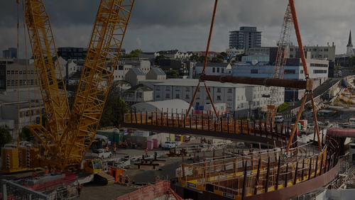
Finally, the photograph on the frontispiece is not of any part of the Auckland Harbour Bridge. The attribution by Auckland Museum is a mistake.
Brian Wilson MA(Cantab), MICE, FEngNZ Site Engineer, on the Auckland Harbour Bridge contract from June 1955 to October 1959.